
What Is the Difference Between iptables Filter, NAT, and Mangle Tables?
Linux iptables is one of the most powerful—and most misunderstood—components of the Linux networking stack. Many administrators learn to “make rules work” without fully understanding why multiple iptables tables exist, how packets move between them, or when to use the filter, NAT, or mangle table. This article provides a clear, technical explanation of the differences between the filter, NAT, and mangle tables in iptables, explaining: Their purpose Where they operate in the packet flow What problems each table is designed to solve Practical, real-world use cases The goal is not just to describe the tables, but to help you choose the right table for the right job. A Quick Overview of iptables Architecture iptables is a user-space interface to the Linux kernel’s Netfilter framework. Netfilter allows packets to be inspected, modified, accepted, dropped, or rerouted at various points during their journey through the kernel. Instead of a single rule list, iptables organizes rules into: Tables (what you want to do) Chains (when you want to do it) Understanding tables is the first step toward understanding iptables correctly. Why iptables Uses Multiple Tables Each iptables table exists to solve a specific category of networking problems. Separating functionality into tables provides: Performance optimization Logical clarity Predictable packet behavior Trying to do everything in one table would make packet handling slow, ambiguous, and error-prone. The Three Most Important iptables Tables While iptables supports several tables (filter, nat, mangle, raw, security), most real-world configurations rely heavily on three: filter – Decide whether packets are allowed or blocked nat – Modify source or destination addresses mangle – Modify packet metadata and headers Each serves a fundamentally different role. The Filter Table: Traffic Allow or Deny Purpose of the Filter Table The filter table is the default and most commonly used table in iptables. Its sole purpose is to permit or block packets. If you think of iptables as a firewall, this is the table that actually acts like a firewall. Common Chains in the Filter Table INPUT – packets destined for the local system FORWARD – packets being routed through the system OUTPUT – packets generated locally What the Filter Table Is Designed For The filter table is designed to answer a single question: Should this packet be allowed to pass or not? Typical use cases include: Allowing SSH access Blocking unwanted ports Restricting traffic by IP Enforcing basic security policies Example: Allow SSH, Block Everything Else iptables -A INPUT -p tcp –dport 22 -j ACCEPT iptables -A INPUT -j DROP This rule set: Allows SSH Blocks all other incoming traffic What You Should Not Do in the Filter Table The filter table is not meant for: Changing IP addresses Marking packets for routing decisions Manipulating packet headers Using the filter table for anything other than accept/drop logic is a design mistake. The NAT Table: Network Address Translation Purpose of the NAT Table The NAT (Network Address Translation) table is used to change packet source or destination addresses. It answers a different question: Where should this packet appear to come from or go to? Common Chains in the NAT Table PREROUTING – before routing decisions OUTPUT – locally generated packets POSTROUTING – after routing decisions What the NAT Table Is Designed For The NAT table exists to: Share a single public IP across many systems Redirect traffic to internal services Expose internal services to external networks Common scenarios: Port forwarding Masquerading Load redirection Example: Port Forwarding iptables -t nat -A PREROUTING -p tcp –dport 80 \ -j DNAT –to-destination 192.168.1.10:80 This rule: Redirects incoming port 80 traffic Forwards it to an internal server Important NAT Behavior: First Packet Only NAT rules apply only to the first packet of a connection. After that, the connection is tracked by conntrack. This is why NAT is efficient—but also why it is not suitable for ongoing packet manipulation. What You Should Not Do in the NAT Table Filtering traffic (use filter) Packet marking for QoS (use mangle) Rewriting packets after routing decisions The Mangle Table: Packet Manipulation & Marking Purpose of the Mangle Table The mangle table is used to alter packet metadata or headers beyond simple address translation. It answers the question: How should the kernel treat this packet? Chains Available in the Mangle Table The mangle table is the most flexible table and supports: PREROUTING INPUT FORWARD OUTPUT POSTROUTING What the Mangle Table Is Designed For Common mangle use cases include: Packet marking Policy-based routing Traffic prioritization QoS classification TTL modification DSCP/TOS changes Example: Packet Marking iptables -t mangle -A PREROUTING -p tcp –dport 443 \ -j MARK –set-mark 1 This mark can later be used by: ip rule tc (traffic control) Custom routing tables Why Packet Marking Matters Packet marking allows administrators to: Route traffic differently Apply bandwidth limits Prioritize critical services Separate workloads on multi-IP systems This functionality cannot be achieved with filter or NAT tables. Packet Flow: How Tables Work Together Understanding packet flow is essential to using iptables correctly. Simplified Packet Flow (Incoming) PREROUTING (mangle → nat) Routing decision INPUT (mangle → filter) Simplified Packet Flow (Forwarded) PREROUTING (mangle → nat) Routing decision FORWARD (mangle → filter) POSTROUTING (mangle → nat) Key Differences at a Glance Feature Filter NAT Mangle Primary Role Allow / block Address translation Packet alteration Default Table Yes No No Packet Marking No No Yes Changes IP Address No Yes No QoS / Traffic Control No No Yes Applied Per Packet Yes First packet only Yes Real-World Scenarios: Choosing the Right Table Scenario 1: Blocking an IP Address → Filter table Scenario 2: Exposing an Internal Web Server → NAT table Scenario 3: Prioritizing API Traffic Over Web Traffic → Mangle table Scenario 4: Multi-ISP Routing → Mangle + ip rule Common Mistakes Administrators Make Using NAT to block traffic Using filter to redirect packets Overloading mangle rules without understanding packet flow Forgetting connection tracking behavior These mistakes often lead to: Unpredictable routing Performance degradation Difficult debugging iptables vs Modern Alternatives While iptables remains widely used, newer systems
How Bandwidth, Throughput & Latency Shape Real-World Performance

There’s a moment from a few years ago I still think about. I was sitting in a freezing server room at 1:30 a.m., wrapped in a jacket that was too thin for the air-conditioning blasting through the vents. The hum of server fans filled the silence. You know that sound — steady, mechanical, almost hypnotic. I had been there for hours, staring at performance graphs on my laptop, trying to understand why a client’s application kept slowing down every evening during peak traffic. CPU usage? Normal.RAM? Barely half used.Disk I/O? Healthy. Yet users were complaining constantly: “It’s lagging.”“Pages are taking forever.”“Everything freezes during checkout.” The technical team was frustrated.The marketing team was panicking.The founder looked exhausted. And there I was, sitting in that cold room, watching packets crawl painfully across the network graph like they were wading through mud. That night, something clicked for me: Servers don’t slow down because they’re weak. They slow down because data can’t move fast enough. Bandwidth.Throughput.Latency. The silent trio that decides whether your app feels fast, sluggish, or completely unusable. Most founders never think about these things.Most engineers underestimate them.Most teams blame the wrong problems. But everything — absolutely everything — in server performance comes back to how efficiently data enters, moves through, and exits your system. This blog is a deep, human-style dive into how bandwidth, throughput, and latency shape server performance. And along the way, I’ll share the lessons that cold night taught me. Let’s begin. Bandwidth: The Highway Size If data were cars, bandwidth would be the number of lanes on the highway. A 1 Gbps NIC means your server has a 1-lane highway capable of moving a certain volume of traffic per second. A 10 Gbps NIC gives you ten lanes. A bonded NIC setup? Even more. People often ask: “Isn’t 1 Gbps enough?” Sometimes yes. Many times, no. Here’s the reality: If your traffic spikes If your app handles large files If your server streams data If your database syncs across nodes If multiple services fight for bandwidth …you will hit congestion. And congestion doesn’t just slow down the heaviest requests.It slows down everything. Think of it like rush hour traffic. Even a small breakdown in one lane affects all the others. That’s what poor bandwidth does to your server. Throughput: The Real Speed Your Server Achieves This is where many people get confused. Bandwidth is the capacity.Throughput is the actual speed. You might have a: 1 Gbps NIC Connected to a 1 Gbps switch On a 1 Gbps network Yet still see only 200 Mbps throughput. Why? Because real-world performance is affected by: Packet loss Congestion NIC driver inefficiencies CPU bottlenecks Application overhead Protocol limitations Poor architecture Throughput tells you: “How fast can data REALLY move?” I’ve seen servers with 10 Gbps NICs perform worse than ancient 100 Mbps setups — simply because throughput wasn’t optimized. Throughput is the heart rate of your application.It tells you how strong your data flow is — not what it should be on paper. Latency: The Invisible Delay That Kills Performance Latency is not about speed.It’s about responsiveness. A server with high bandwidth but high latency?Feels slow. A server with low bandwidth but low latency?Feels snappy. Latency is the time it takes for a packet to: Leave your server Reach the destination Come back with confirmation It’s the “lag” users feel. Latency issues show up as: Click delays Slow page loads Timeout errors Jitter in voice/video Delayed database queries Latency comes from: Distance Routing hops Queueing delays Kernel processing NIC buffering Low latency = smoother experience.High latency = angry customers. Packet Flow: The Journey Your Data Takes Every packet that moves through your server experiences a journey. Step 1: Packet enters via NIC NIC reads the electrical/optical signal and processes it. Step 2: NIC hands packet to kernel Kernel processes metadata and queues it. Step 3: Kernel passes packet to application Your app reads, parses, and acts on the data. Step 4: Response packet flows back App → Kernel → NIC → Network → Client If ANY step is slow, everything becomes slow. A congested NIC = slow data intake.A busy kernel = slow routing.A saturated CPU = slow packet processing.A poorly optimized app = slow response creation. This is why server optimization is so critical.Packets don’t lie.They tell you exactly where the bottleneck is. NIC Speeds: The Unsung Heroes of Performance Network Interface Cards (NICs) are often ignored — until they become the bottleneck. NIC speeds determine how quickly your server can: Receive requests Send responses Sync data Communicate with databases Handle microservices A 1 Gbps NIC struggles under: High-traffic APIs Large file uploads Streaming workloads E-commerce traffic spikes Multi-service architectures Enterprises prefer: 10 Gbps 25 Gbps 40 Gbps NIC bonding for redundancy and higher throughput A single NIC upgrade can transform server performance overnight. Real-World Impact: What Users Actually Feel Here’s the big truth: Users don’t see bandwidth, throughput, or latency — they see your app being fast or slow. Bandwidth shortage feels like: Pages loading slowly Video buffering Slow downloads Throughput limits feel like: Random delays Congested performance Backend bottlenecks High latency feels like: Clicks lagging Forms taking too long Slow login responses Your infrastructure shapes the emotional experience of your user. And that matters far more than most people admit. When Bandwidth Lies to You One night, during another investigation, we saw the NIC graph at only 30% usage.Yet users were complaining of a “slow” site. We discovered: The bandwidth wasn’t the issue.The packet retransmissions were. When packets get lost, the server sends them again.This reduces throughput dramatically. So yes — your NIC may not be maxed out…But your application still feels painfully slow. That day I understood: Looking at bandwidth alone is like diagnosing a fever without checking why it exists. How These Elements Work Together This is where the magic happens. Bandwidth = potential The maximum lane size available. Throughput = reality How much traffic your system actually handles. Latency = responsiveness How quickly your
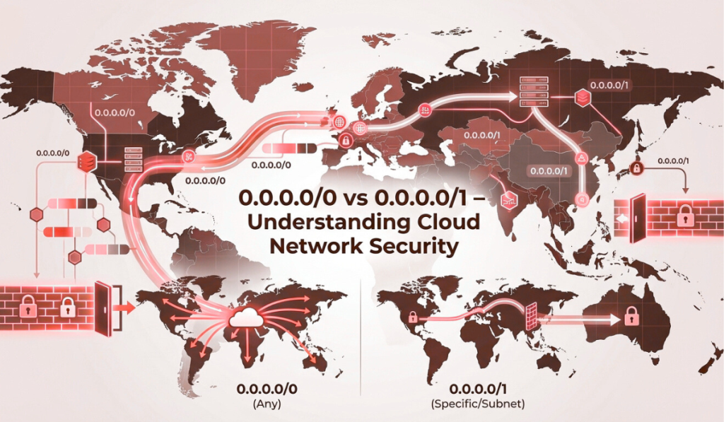
0.0.0.0/0 vs 0.0.0.0/1 – The Networking Difference That Can Make or Break Your Cloud Security
In cloud and hosting environments, some of the most dangerous mistakes don’t come from complex systems. They come from small configuration choices. A single CIDR block.One routing rule.One firewall entry that “just works.” And among the most misunderstood of these is the difference between 0.0.0.0/0 and 0.0.0.0/1. On the surface, they look nearly identical.Both start with 0.0.0.0.Both appear to cover large IP ranges. But in practice, they behave very differently. In modern cloud infrastructure—whether you’re running workloads on virtual machines, dedicated servers, private networks, or hybrid setups—understanding these two CIDR ranges is essential. A misunderstanding here can lead to: Open security exposure Incorrect routing Broken VPN tunnels Unexpected traffic leaks Compliance failures At Purvaco, we often see businesses running stable applications while unknowingly carrying risky network configurations underneath. This guide exists to remove that confusion. By the end of this article, you’ll clearly understand: What 0.0.0.0/0 and 0.0.0.0/1 actually mean How they differ in routing, firewall rules, and VPNs When to use each safely Why cloud environments magnify their impact Understanding CIDR Notation (Without Overcomplicating It) Before comparing the two, we need to understand CIDR notation in simple terms. CIDR stands for Classless Inter-Domain Routing.It’s a way to describe how large an IP range is. The format looks like this: IP_Address / Prefix_Length The number after the slash (/) defines how many leading bits are fixed for the network portion. The rule is simple: Smaller number after the slash = larger network Larger number after the slash = smaller network Example: /32 → one single IP address /24 → 256 IP addresses /16 → 65,536 IP addresses /0 → the entire IPv4 internet This is where the confusion starts. What Exactly Is 0.0.0.0/0? 0.0.0.0/0 is the largest possible IPv4 network. It includes every IPv4 address, from: 0.0.0.0 to 255.255.255.255 Nothing is excluded. Because of this, 0.0.0.0/0 is commonly referred to as: The default route The catch-all route The entire internet What It Means in Practice When a system sees 0.0.0.0/0, it interprets it as: “If you don’t have a more specific rule, apply this one.” This makes it extremely powerful—and extremely dangerous if misused. Common Use Cases of 0.0.0.0/0 1. Default Routing in Cloud Networks In routing tables, 0.0.0.0/0 is used as the default gateway. If traffic doesn’t match a more specific route, it is sent through this default route—often toward the internet gateway. This is normal and necessary for outbound internet access. 2. Firewall and Security Group Rules In firewalls, 0.0.0.0/0 means: “Allow traffic from anywhere.” For example: SSH open to 0.0.0.0/0 HTTP open to 0.0.0.0/0 This is one of the most common cloud security mistakes. While public services like websites may require this, sensitive services should almost never be exposed this way. 3. NAT and Internet Access Outbound NAT rules often use 0.0.0.0/0 to indicate that traffic to any external destination should be translated and forwarded. This is normal for internet-bound traffic. The Security Reality of 0.0.0.0/0 0.0.0.0/0 is not bad by itself. The risk comes from where and how it’s used. If applied to: Inbound firewall rules Management ports Internal services It effectively removes all network-level protection. At Purvaco, one of our core hosting security practices is to minimize the use of 0.0.0.0/0 in inbound rules and replace it with: Office IP ranges VPN ranges Bastion hosts Private networks What Is 0.0.0.0/1? Now comes the less familiar cousin. 0.0.0.0/1 represents half of the IPv4 address space. Specifically: 0.0.0.0 – 127.255.255.255 Only addresses where the first bit is 0 are included. The remaining half of the internet is covered by: 128.0.0.0/1 Together, these two /1 blocks split the internet cleanly into two equal halves. Why 0.0.0.0/1 Exists at All At first glance, /1 networks feel odd. Why not just use /0? The answer lies in routing control. Practical Use Cases of 0.0.0.0/1 1. Traffic Splitting and Advanced Routing In complex routing scenarios, engineers sometimes want to: Override the default route Split traffic across gateways Control which destinations go where Instead of one /0 route, they define: 0.0.0.0/1 → Gateway A 128.0.0.0/1 → Gateway B This allows fine-grained routing decisions without using /0. This is common in: Multi-WAN setups Advanced cloud routing Hybrid networks 2. VPN Split Tunneling One of the most common real-world uses of 0.0.0.0/1 is in VPN configurations. Rather than forcing all traffic through a VPN, administrators may: Send half the traffic through VPN Leave half outside Combine /1 routes strategically This avoids conflicts with existing default routes. 3. More Controlled Firewall Policies While 0.0.0.0/0 allows everything, 0.0.0.0/1 allows only half. This can be useful in: Transitional security policies Geo-based filtering strategies Layered firewall designs It’s not common for beginners—but very powerful for advanced setups. Key Differences Between 0.0.0.0/0 and 0.0.0.0/1 Aspect 0.0.0.0/0 0.0.0.0/1 IP Coverage Entire IPv4 space Half of IPv4 space Size Largest possible 50% of internet Typical Use Default routes, NAT, public access Traffic splitting, VPN routing Security Risk Very high if misused More controlled Cloud Usage Very common Advanced configurations Best Practice Use cautiously Use intentionally Why Cloud Environments Amplify the Risk In traditional on-prem networks, mistakes are often contained. In cloud environments, they are instantly global. A misconfigured 0.0.0.0/0 firewall rule doesn’t just expose a server—it exposes it to the entire internet within seconds. This is why managed cloud hosting platforms like Purvaco emphasize: Principle of least privilege Minimal exposure Layered security controls Careful CIDR planning Which One Should You Use? Use 0.0.0.0/0 When: Defining a default route to the internet Allowing public web traffic (HTTP/HTTPS) Configuring outbound NAT rules And only when protected by: Firewalls Application-level security Monitoring Use 0.0.0.0/1 When: Splitting traffic across gateways Building advanced VPN routing Avoiding default route conflicts Implementing controlled routing logic This is not a beginner-level configuration—but extremely useful when used correctly. Common Misconfigurations We See in Real Projects At Purvaco, some of the most frequent issues include: SSH open to 0.0.0.0/0 Databases exposed publicly VPN routes overriding production traffic Duplicate default routes causing outages These issues don’t happen because teams are careless.